Remote Controlled Robot Using Arduino And T.V. Remote
This remote controlled car can be moved around using practically any kind of remote such as TV,AC etc.
It makes use of the fact that the remote emits IR(infrared).
This property is made use of by using an IR receiver,which is a very cheap sensor.
In this instructable you will learn how to
- Interface IR receiver to Arduino.
- Interface 2 motors to Arduino.
- Combine the above 2 setups.
Note:This remote controlled car has a disadvantage of not work outside in sunlight.
All the code, schematics and other pictures at one place are here.
Step 1: Materials Required
- Arduino Uno and USB cable
- Arduino software
- Breadboard
- 100rpm dc motors
- IR receiver(SM0038 or TSOP1738)
- L293D motor driver IC
- Jumper wires
- Chassis and wheels
- 9V batteries(2 nos)
- Battery clips
Total cost of materials:Rs 600=$ 9(excluding cost of Arduino)
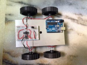
Fix the wheels to the chassis.
Attach the 2 motors to the back wheels and use dummies for the front.
Make holes on the chassis and fix Arduino using screws.
Fix the breadboard by using the double sided tape provided on it.
Mount the L293D on the breadboard with notch facing front.
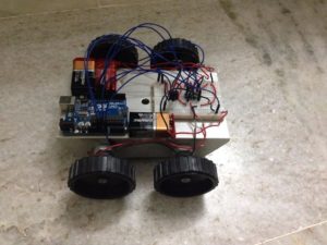
Step 2: Assembly
Fix the wheels to the chassis.
Attach the 2 motors to the back wheels and use dummies for the front.
Make holes on the chassis and fix Arduino using screws.
Fix the breadboard by using the double sided tape provided on it.
Mount the L293D on the breadboard with notch facing front.
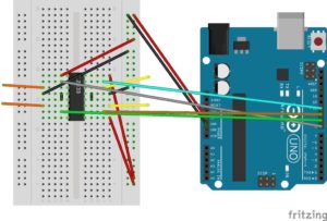
Step 3: IR Receiver Connections
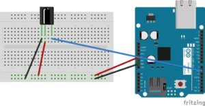
Facing the notch on the receiver, the connections from left to right are
- left pin-ground.
- middle pin-5V.
- right pin-digital pin 6 on Arduino.
Refer to the schematic for more details.
Step 4: Saving the IR Library
Go to the following link-
Step 5: Getting Hex values

Save the files within a folder named IRremote and save the folder in the libraries directory of your Arduino IDE i.e. arduino-1.0.6>libraries folder as IRremote.
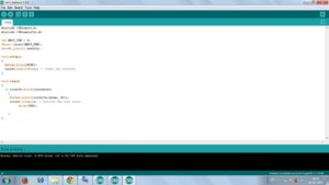
- Upload the code in remote.ino into the Arduino
- Open the serial monitor.
- Press different remote keys and obtain their hexadecimal values.(Note that the values will not be obtained with 0x which represents hexadecimal also some values are obtained in middle like FFFFFFFF, ignore them).
Here I have obtained the values of the front,back,left,right and middle keys which are
front=0x80BF53AC
back=0x80BF4BB4
left=0x80BF9966
right=0x80BF837C
middle=0x80BF738C
These values of these buttons are mapped to move front,move back,move left,move right and brake respectively.
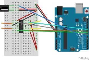
Step 6: L293D Connections
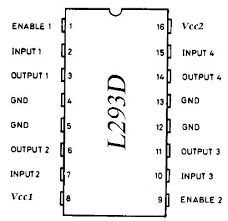
Take 5V and ground from Arduino and connect them to the 2 bottom rails of breadboard,thus giving a 5V and ground line.
Pins 1,9,16 from L293D to 5V.
Pins 4,5,12,13 from L293D to ground.
Left motor to pins 3,6 on L293D.
Right motor to pins 11,14 on L293D.
Pins 2,7(for left motor)from L293D to pins 9,8 on Arduino.
Pins 10,15(for right motor)from L293D to 10,11 pins on Arduino.
Refer to schematics for more details.
Note that in the schematic yellow wires represent left motor and orange wires right motor.
Step 7: Interfacing Motors With L293D
After making the connections,upload the code in motor_test.ino into the Arduino.
Note that for left motor to rotate, lm,lmr should be opposite i.e HIGH and LOW or vice versa. .
Similarly for right motor to rotate, rm,rmr should be opposite i.e HIGH and LOW or vice versa.
Determine the logic levels of lm,lmr,rm,rmr for both the wheels to go forward by trial and error.
For me it was LOW,HIGH,HIGH,LOW.
Thus the inputs required to go forward are LOW,HIGH,HIGH,LOW.
Inputs required to go backward are HIGH,LOW,LOW,HIGH.
Inputs required to go right are LOW,HIGH,HIGH,HIGH(i.e. only left motor should rotate).
Inputs required to go left are HIGH,HIGH,HIGH,LOW(i.e. only right motor should rotate).
Note that values of lm,lmr,rm,rmr obtained may be different from above.
Step 8: Integrating Everything
Now integrate everything i.e. both the ir receiver part and L293D part.
The schematic given above is just a combination of schematics of IR receiver and L293D.
Basically you can first make the IR connections, find hexadecimal value and without disturbing the IR connections, make the L293D connections and interface the motors with Arduino.
Step 9: Power Supply
9V powering the Arduino with positive of battery given to vin pin of Arduino and negative given to the second ground pin of Arduino
9V for Vss supply(pin 8) of l293d which is used for driving the motors(max value that can be given is 36V)
Step 10: Final Program
Upload the code given in rc_car.ino into the Arduino(provided both IR and L293D connections have been made).
The code just like the previous schematic is just an integration of remote and motor test codes i.e. the Arduino first now checks the remote key which you have pressed by obtaining its hexadecimal value ,checks what function has been mapped to that value and performs the required function through L293D
Check if the bot moves as required or not.
Go to this repository to download the code and schematics.Click on the “Clone or Download” button (green in color on the right side) and select “Download ZIP” to download the zip file.Now extract the contents on your computer to get the code and schematics(in the schematics folder).
Step 11: How the Bot Works
Here is a video of the bot in motion.