Beginner’s Guide To ESP8266 and Tweeting Using ESP8266
I learnt about Arduino 2 years ago.So I started playing around with simple stuff like LEDs,buttons,motors etc.Then I thought wouldn’t it be cool to connect to do stuff like displaying the day’s weather,stock prices ,train timings on an LCD display.I found that this could be done by sending and receiving data through the internet.So the solution was connecting to intenet. There began my search on how to connect the Arduino to internet and send and receive data.I learnt about wifi modules on the internet and found them to be very costly.Then I learnt of the ESP8266.
I read a lot on the internet on the ESP8266 module about a year ago and bought one but got about to work with them just last month.At the time there was no extensive information available.However now a lot of documentation,videos are are available on the internet regarding firmware,AT commands,projects etc.So I decided to get started.
I wrote this instructable as a beginner’s guide as I faced a lot of problems in wiring up and getting started with the ESP8266.So I decided to write this Instructable so that other people who encounter problems with their modules can resolve them faster
In this Instructable I will try to show
- How to hookup an ESP8266 and communicating with it through Arduino Uno.
- I will also try to show how a tweet can be sent through it using Thingspeak.
What can the ESP8266 do?It is limited by your imagination.I have seen projects and tutorials on the internet showing how to fetch a city’s temperature, stock prices,sending and receiving emails ,making phone calls and much much more.I will show in this Instructable how to send a tweet.
Step 1: Things You Will Need
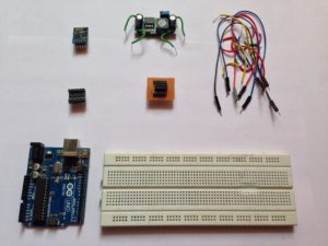
Here are the things you will need.Most of these may be bought from any electrical store or online(I have provided the links for reference).
- 1xESP8266(ESP-01)
- 1xBreadboard adapter(learn how to make one here or use some jumper wires)
- 1xLM2596
- 1xLogic level converter
- 1xArduino Uno
- USB cable for Arduino Uno
- 1xBreadboard
- Wires
- Arduino IDE
- An account with Thingspeak
The total cost will be around Rs 600(about $9).I have excluded the cost of Arduino Uno as it depends on whether you want an original or a clone.The cheapest clones are available at around Rs 500(about $4).
Step 2: Some Info on ESP8266
ESP8266 was launched in 2014 just a year ago so it is quite new.The chips are manufactured by Espressif .
The greatest advantage of ESP8266 is perhaps its cost.It is quite cheap and you can buy a couple of these at a single go.Before I came to know about it I couldn’t even think of buying a wifi module.They were too costly. New versions of ESP8266 are being released quite frequently and the latest one is ESP 12.However in this Instructable I will focus only on ESP 01 which is quite popular.Moreover when you buy the ESP8266 it comes pre loaded with the default AT firmware.So you are good to get started as soon as you buy one..Also as you will see from this instructable it is quite easy to interface them.
Every device has its own advantages and disadvantages and ESP is no different.The ESP may prove sometimes to be very tricky and frustrating to work with.Since it is quite new you will find it difficult to obtain information about it.Fortunately a community at esp8266.com exists which is a lot of help.Moreover it also sometimes also starts doing unexpected things like throwing up a load of garbage through the serial connection etc.
Note that there is a lot of documentation available on the internet and some part of it is conflicting.This Instructable is no different.While playing around with my ESP8266 I found that it did deviate a lot from what was mentioned on the internet(yours may too) but it worked fine.
Step 3: Pinout of ESP8266
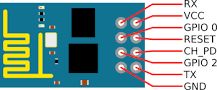
The ESP8266 has 8 pins as shown.
Gnd and Vcc should be connected as usual to the ground and supply respectively.The ESP8266 operates on 3.3V.
RESET pin is used to manually reset the ESP.It should normally be connected 3.3V.If you want to reset the ESP connect this pin to ground momentarily and then back to 3.3V.
CH_PD is the chip power down which should be normally connected to 3.3V.
GPIO0 and GPIO2 are general purpose input output pins.These should be normally connected to 3.3V.However when flashing the firmware connect GPIO0 to gnd.
Rx and Tx pins are the transmitting and receiving pins of ESP8266.They operate on 3.3V logic i.e. 3.3V is logic HIGH for ESP8266.
Detailed connections are provided in later steps.
Step 4: What Should Be Used for Communicating With ESP8266?
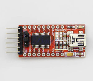
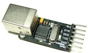
There are a lot of devices that can be used to communicate with ESP8266 such as FTDI programmers,USB to TTL serial converter ,Arduino etc.However I have used an Arduino Uno simply because it is the easiest and almost everyone has it.Also if you have an Arduino you also have the Arduino IDE and its serial monitor can be used for communication with the ESP8266.So no spending money on FTDI programmers etc.
However if you want or if you already have one,you may use an FTDI programmer or a USB to TTL serial converter(more on how to connect them later).Also there are a lot of software such as RealTerm or putty.You may use these in the same way as the Arduino IDE’s serial monitor.
Step 5: Mounting the ESP8266 on Breadboard
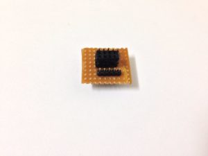
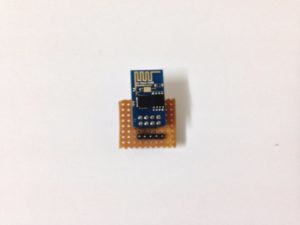
Notice that the pins of ESP8266 are not breadboard friendly.This can be overcome by 2 ways.
Use female to male jumper wires which can make things messy or
Do as shown in this Instructable or
Use an adapter board , make one yourself(there are a lot of them on Instructables) which is neat.
Step 6: Power Supply
The ESP8266 works on 3.3V supply.Don’t connect it to the 5V pin on Arduino.It will probably burn.
Some tutorials suggested making a voltage divider circuit using 1k,2k resistors with 5V as input and obtaining 3.3V across the 2k resistor and supplying it to the Arduino.However, I found that the ESP didn’t even power up when I did this.
I was able to power it up using the 3.3V on Arduino,but found that the ESP got hot after some time.
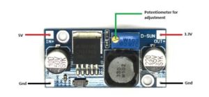
You can use a 3.3V voltage regulator.
Or you can use LM2596 dc-dc step down converter.These are quite cheap.and I used these.Give 5V from Arduino to the input.Adjust the potentiometer on the module,until the output becomes 3.3V.I found that the ESP can be powered from one of these for hours.Make the connections as shown in the figure.
Step 7: Logic Level Conversion
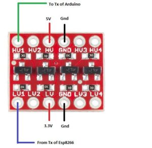
It is mentioned that the ESP has 3.3V logic while the Arduino has 5V logic.
This means that in the ESP 3.3V is logic HIGH while in Arduino 5V is logic HIGH.This may cause some problems while connecting them together.
I found on internet that logic level conversion needs to be applied while interfacing ESP Rx and Tx with Arduino .
Some tutorials mentioned that logic level conversion is needed while interfacing ESP Rx pin.
However I found that just normally connecting the ESP Rx and Tx pins to the Arduino did not cause any problems.
I connected Rx and Tx through logic level converter as well as Rx alone but did not obtain any response.
However I found that connecting ESP Tx pin through logic level converter while connecting the Tx directly also caused no problems.
So logic level converter may or may not be used.
Use whichever method that works for you through trial and error.
Step 8: Connections
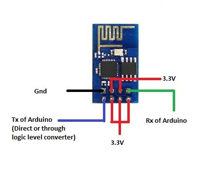
The connections of ESP8266 are:
ESP8266
Gnd -> Gnd
GPIO2 -> 3.3V
GPIO0 -> 3.3V
Rx -> Rx of Arduino
Tx -> Tx of Arduino(direct or through logic level converter)
CH_PD -> 3.3V
RESET -> 3.3V
Vcc -> 3.3V
(Note that in some versions ESP Rx should be connected to Arduino Tx and ESP Tx should be connected Arduino Rx).
If you are using FTDI programmer or USB to TTL serial converter,connect their Tx and Rx to Rx and Tx of ESP8266 respectively.
Step 9: Getting Started
After making the connections,upload
void setup()
{}
void loop()
{}
i.e. a blank sketch to the Arduino..
Open the serial monitor and set it to “Both NL & CR”.
Experiment with the Baud rate.It should usually be 9600 though sometimes it may be 115200.
Step 10: AT Commmands

Simply saying AT commands are commands that can be sent to the ESP8266 so as to enable it to perform some functions such as restart,connect to wifi etc.The ESP in response will send some confirmation in the form of text.Below I have explained some AT commands and how the ESP responds to them.Note that by send I mean typing in the command and hitting enter(return).
- Send AT through the serial monitor.
This command is used as a test command.
How the ESP responds:OK should be returned.
- Send AT+RST through the serial monitor.
This command is used to restart the module.
How the ESP responds:ESP returns a load of garbage.However look for Ready or ready.
- Send AT+GMR through the serial monitor.
This command is used to determine the firmware version of the module.
How the ESP responds:Firmware version should be returned.
Firmware is a piece of software that is installed on a device usually on its ROM(read only memory) i.e. it is not meant to be changed frequently or not at all.It provides the control and data manipulation of the device.ESP8266 has a number of different firmwares all of which are quite easy to flash(install).
Step 11: General Syntax of AT Commands
The general syntax of AT commands for performing different functions is given:
- AT+parameter=?
When a command in this type is sent through the serial monitor,the ESP returns all the values that parameter can take. - AT+parameter=val
When a command in this type is sent through the serial monitor,the ESP sets the value of parameter to val. - AT+parameter?
When a command in this type is sent through the serial monitor,the ESP returns the current value of parameter.
Some AT commands may take only one of the above types while some may take all 3.
An example of a command that is possible in all the above 3 types is CWMODE,which is used to set the wifi mode.
- Send AT+CWMODE=? through the serial monitor.
How the ESP responds:All the values that the ESP CWMODE can take(1-3) are returned specifically +CWMODE(1-3).Where
1=Static
2=AP
3=Both static and AP
- Send AT+CWMODE=1 through the serial monitor.
How the ESP responds:OK should be returned if there is a change in the CWMODE from it’s previous value and it is set to static, else no change should be returned if there is no change in CWMODE value.
IMPORTANT:Unless CWMODE is set to 1,the commands in the later steps will not work.
- Send AT+CWMODE? through the serial monitor.
How the ESP responds:The present value of CWMODE should be returned,specically if you followed the above step +CWMODE:1 should be returned.
Step 12: Connecting to Wifi
- Send AT+CWLAP through the serial monitor
This command is used to list out all the networks in the area.
How the ESP responds:A list of all the available access points or wifi networks should be returned.
- Send AT+CWJAP=”SSID”,”password”
(including the double quotes).
This command is used to join a wifi network.
How the ESP responds:OK should be returned if the module has been connected to the network.
- Send AT+CWJAP? through the serial monitor
This command is used to determine the network to which the ESP is currently connected.
How the ESP responds:The network to which the ESP is connected will be returned.Specifically +CWJAP:”SSID”
- Send AT+CWQAP through the serial monitor
This command is used to disconnect from the network to which the ESP is currently connected.
How the ESP responds:The ESP quits the network to which it is connected and OK is returned.
- Send AT+CIFSR through the serial monitor
This command is used to determine the IP address of the ESP.
How the ESP responds:The IP address of the ESP is returned.
Step 13: Thingspeak
If you haven’t made an account on Thingspeak make one now.
After making an account on Thingspeak go to Apps>ThingTweet.
Link your twitter account with it.
Note the API key that is generated.
Here after the ThingTweet app has been used to link a Twitter account to your ThingSpeak account,you may send a tweet using the TweetContol API .
An API(application program interface) is code that allows two software programs to communicate with each other.
Some other APIs that are available to developers are Google maps API,Open weather API etc.
Only after the ESP has been set up,checked and connected to wifi (basically all the steps given in previous 2 steps) ,go through the steps given below
Step 14: Some More AT Commands
- Send AT+CIPMODE=0 ,through the serial monitor
How the ESP responds:OK is returned.
The CIPMODE command is used to set the transfer mode.
0=normal mode
1=UART-WiFi passthrough mode
- Send AT+CIPMUX=1 through the serial monitor
How the ESP responds:OK is returned.
The CIPMUX command is used to set single or multiple connections.
0=single connection
1=multiple connection
Step 15: Setting Up the TCP Connection

Note that starting from the first command,as soon as you send the first one,the connection will be established for a limited time only.So send the commands as quickly as possible.
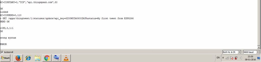
- Send AT+CIPSTART=0,”TCP”,”api.thingspeak.com”,80 through the serial monitor
How the ESP responds:Linked is returned if the connection has been established.
This command is used to establish a TCP connection.
The syntax is AT+CIPSTART=link ID,type,remote IP,remote port
where
link ID=ID of network connection (0~4), used for multi-connection.
type=string, “TCP” or “UDP”.
remote IP=string, remote IP address(address of the website).
remote port=string, remote port number( usually selected to be 80).
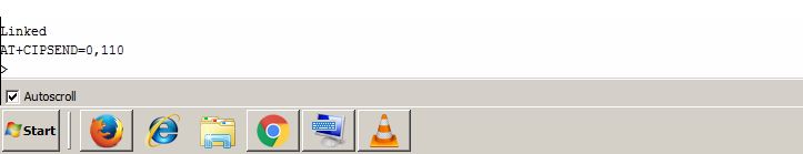
- Send AT+CIPSEND=0,110 through the serial monitor
How the ESP responds:> (greater than) is returned if the command is successful.
This command is used to send data.
The syntax is AT+CIPSEND=link ID,length
where
link ID=ID of the connection (0~4), for multi-connect.Since CIPMUX has been set to 1, is 1.
length=data length, MAX 2048 bytes.Generally choose a large number for the length.
Step 16: Sending the Tweet
Now for sending the tweet
Send GET /apps/thingtweet/1/statuses/update?api_key=yourAPI&status=yourtweet through the serial monitor.
Replace yourAPI with the API key and yourtweet with any tweet that you desire.
As soon as you send the above command start pressing the enter(return) at approximately 1 second intervals.After some time, SEND OK,+IPD,0,1:1 and OK will be returned which means that the tweet has been posted.
Open your twitter and check whether the tweet has been posted or not.
Also note the same tweet cannot be sent repeatedly.
The above string that was sent (GET….), is a HTTP GET request.
The GET request is used to retrieve data from the given server(api.thingspeak.com).
Step 17: What to Do After This
View on YouTube
Go to this repository to download the code and schematics.Click on the “Clone or Download” button (green in color on the right side) and select “Download ZIP” to download the zip file.Now extract the contents on your computer to get the code and schematics(in the schematics folder).I have also uploaded a cheatsheet, which summarizes all the AT commands, to this repository.
There are a lot of great resources available on the internet dealing with ESP8266 .I have mentioned some of them here:
You may also experiment more with AT commands.There are a lot of APIs that are available on the internet that can do all sorts of things such as get the weather,stock prices etc.